asset-guides
Roof Generator
Full guide to the iMeshh Roof Generator for Blender, covering the tile and metal panel systems, attributes, trim methods, ridges, gutters, snow guards, moss, camera culling, and texture painting.
Updated 9 July 2026
The iMeshh Roof Generator creates a variety of roof types in Blender, including metal panel roofs and tile roofs. You model a simple base mesh for the roof shape, add the generator, and it builds the tiles, ridges, gutters, and trim procedurally.
Some parameters are shared between the tile and metal roof systems, and some are unique to each type. This guide covers both.
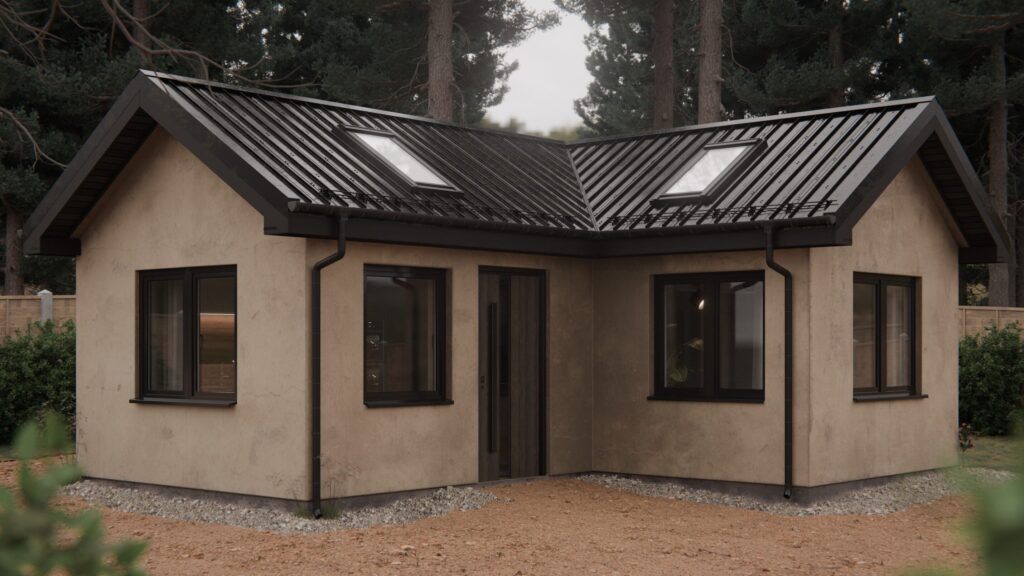
Differences between metal and tile roof types
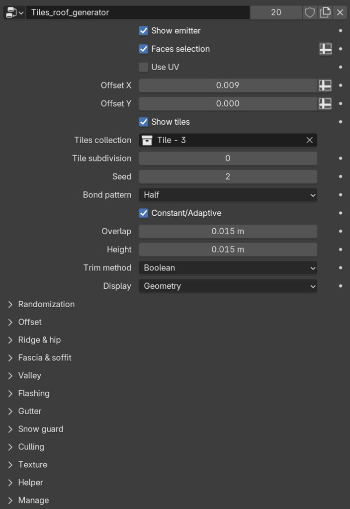
Tile Roof Generator
Metal Panel Roof Generator
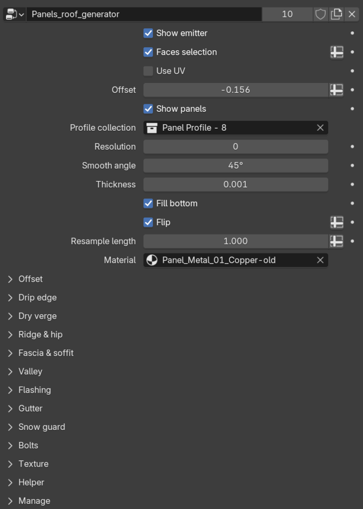
The most obvious difference is that the tile generator uses a collection of geometry for its tiles, while the metal panel generator uses a profile curve. The sections below cover each system's parameters in detail.
Attributes
Introduction to attributes
Both roof systems use attributes, so it makes sense to cover this first.
Attributes are a bit like vertex groups: you assign vertices, edges, or faces to a specific data type, such as a boolean or a float value, which lets you fine-tune the roof system per element instead of globally.
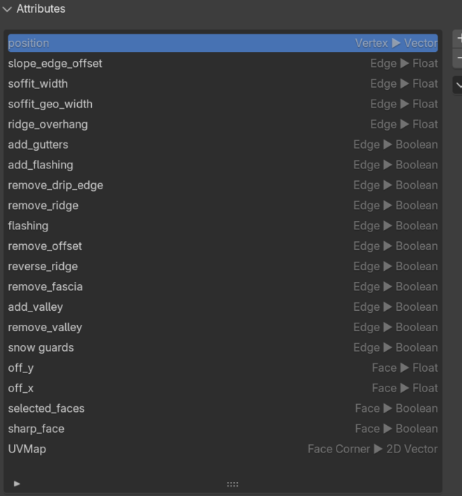
You can create your own attributes with any name, but the roof generators come pre-configured with a set of attributes that work out of the box. You can find them in the Object Data Properties tab under Attributes.
If you see this button next to an input in the geometry nodes modifier (the Input Attribute Toggle), it means the input can be driven per element rather than applied to the whole roof.

How to use attributes
A real example. The parameter Ridge Overhang has an input value of 0.049, which means every ridge in the system gets exactly the same overhang. Next to it is an Input Attribute Toggle button.
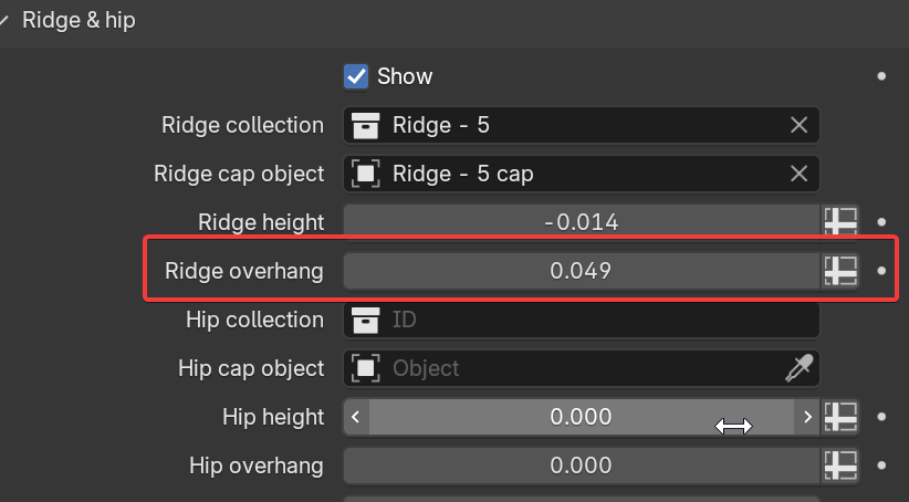
Click the toggle and the field becomes empty: no attribute is assigned yet, so we can add one. Type a name such as ridge_overhang. It is best to name the attribute the same as the parameter so it stays easy to understand.
As you type, Blender suggests the existing ridge_overhang attribute from Object Data Properties, since the generator ships with it already set up. Click it.
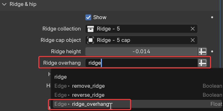
The roof system now reads each ridge's overhang from the attribute. Next, tell Blender which edges carry the attribute and how much overhang each one gets.
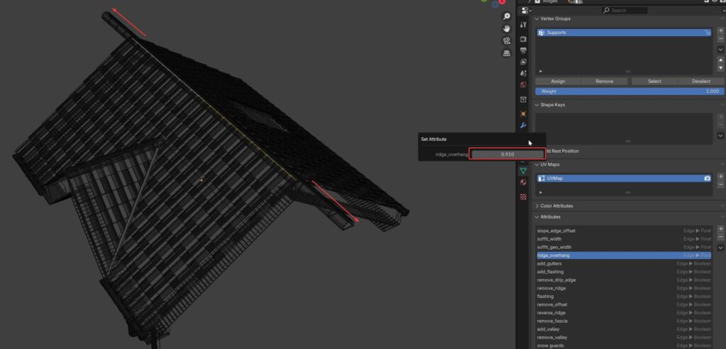
In the Object Data Properties tab, select the ridge_overhang attribute. It is assigned to the Edge domain, which makes sense because ridges sit on the edges of the object.
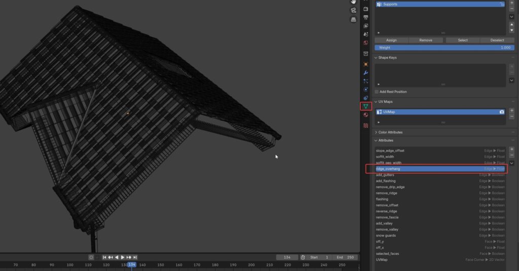
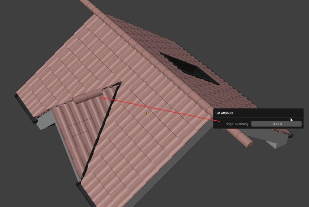
Go into Edit Mode, select the edge you want to adjust, keep the attribute selected, press F3, and search for Set Attribute. Now you can give that edge its own overhang value, for example 0.91.
Here the other ridge edge gets another unique value:
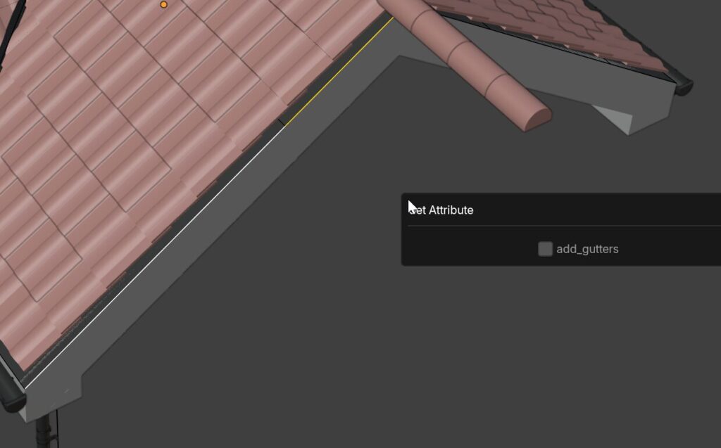
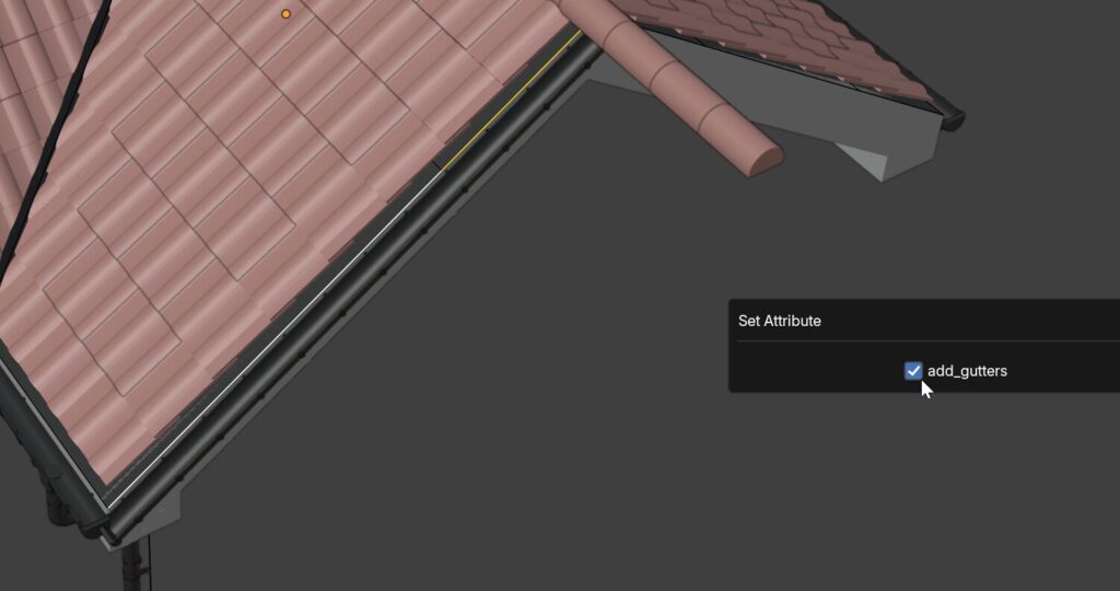
Another example. Under Gutters there is an already exposed attribute called add_gutters. Find it in the Object Data Properties tab, go into Edit Mode, select the edges you want gutters on, press F3, and run Set Attribute. This one is a boolean checkbox (an on/off switch) instead of a float value like before (a float is a number with a decimal point, useful for lengths and offsets).
The same pattern applies to face-based attributes: for Face Selection, use the selected_faces attribute, go into Edit Mode, select the faces you want, and assign them. Only those faces get tiles.
Tile Roof Generator
Now that attributes are covered, here is every parameter in the tile roof system.
Initial settings
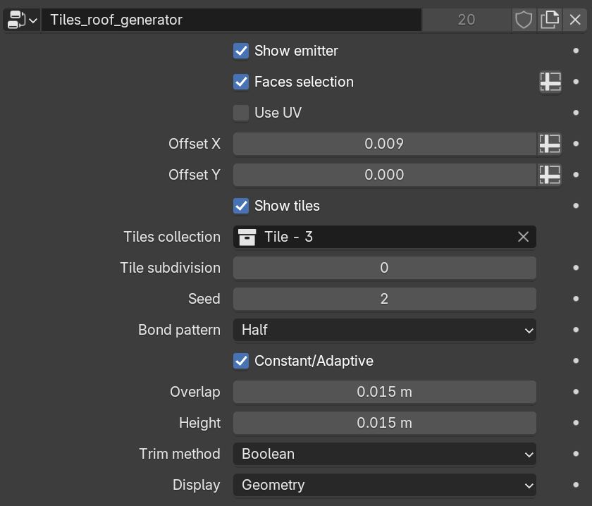
- Show Emitter: hide or show the original base geometry used for the roof system.
- Face Selection: click the Input Attribute Toggle, use the selected_faces attribute, go into Edit Mode, select the faces you want, then assign them in Object Data Properties. Only assigned faces get tiles.
- Use UV: use the UV map itself to control tile locations and orientations. Make sure the roof base mesh is unwrapped and your UV islands sit at 90-degree increments, or the tiles will run at the wrong angles.
- Offset X and Y: shift the tiles along the X and Y plane. To see a visible difference on Offset Y, disable Constant/Adaptive (explained below).
- Show Tiles: show or hide the tiles.
- Tiles Collection: choose the collection for the tiles. The collection can hold multiple tiles and the system randomises through them.
- Tiles Subdivision: useful if the boolean trim method is struggling. Adding more geometry to the tiles can fix boolean errors.
- Seed: change the seed of the tile randomisation.
- Bond Pattern: choose between Half, Straight, and Quarter. Some roof tiles need Half to work correctly.
- Constant/Adaptive: on by default. The system always tries to fit a whole number of tiles along the Y axis, which is useful if tiles are being cut in half at the top or bottom. Disable it to shift tiles freely without snapping to full tile sizes.
- Overlap: how much each tile overlaps the next. Some tiles are built to overlap, others are not.
- Height: move the tiles up away from the roof base geometry.
- Trim Method: more involved, covered in the next section.
Trim methods
None. No boolean happens at the edges.
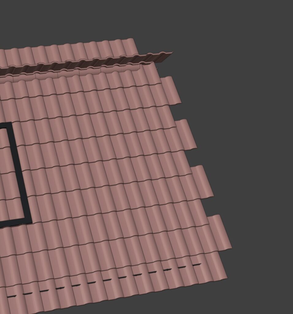
Boolean. The most accurate method, but it can be slow to calculate, especially with complex geometry. If some parts fail to cut correctly, add more Tiles Subdivision to increase the geometry, which helps the boolean.
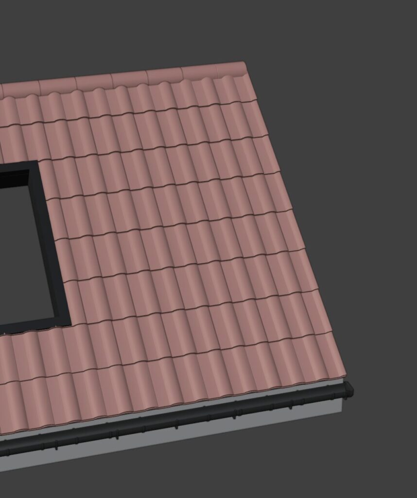
Alpha Map. In the viewport this looks just like None, but in rendered preview the edges are cleaned up by transparency. The benefit is better viewport performance; the trade-off is that solid view looks rough.
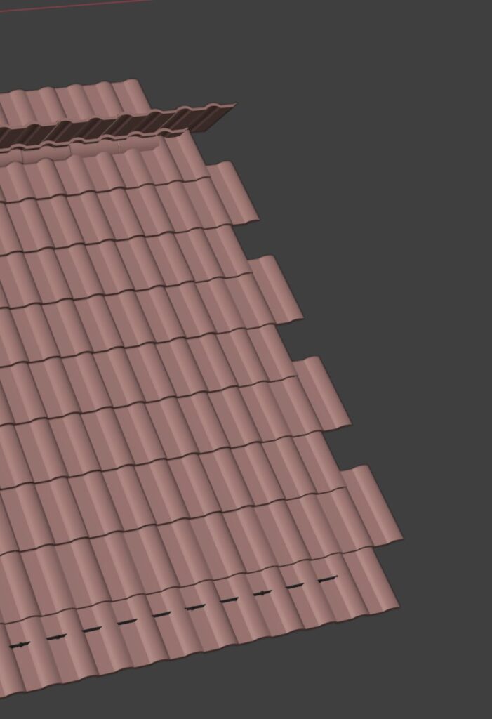
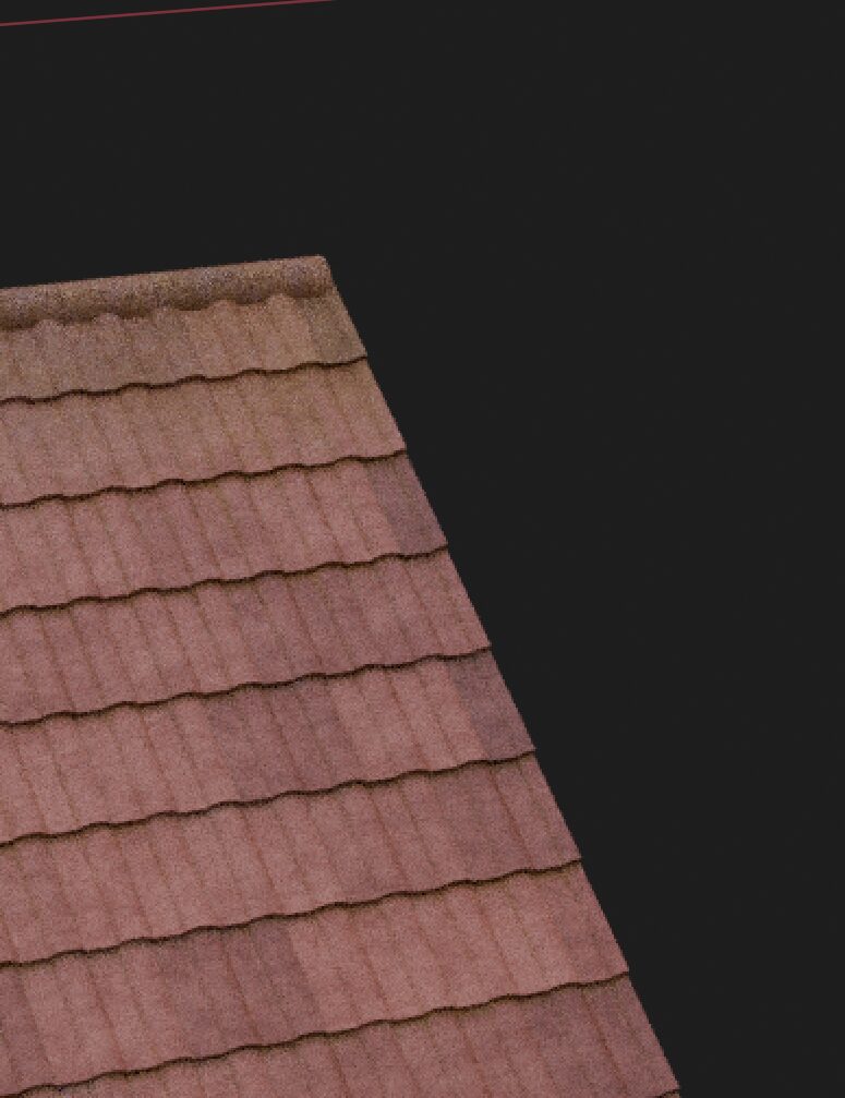
You may get errors with this method; if so, add subdivisions to your model.
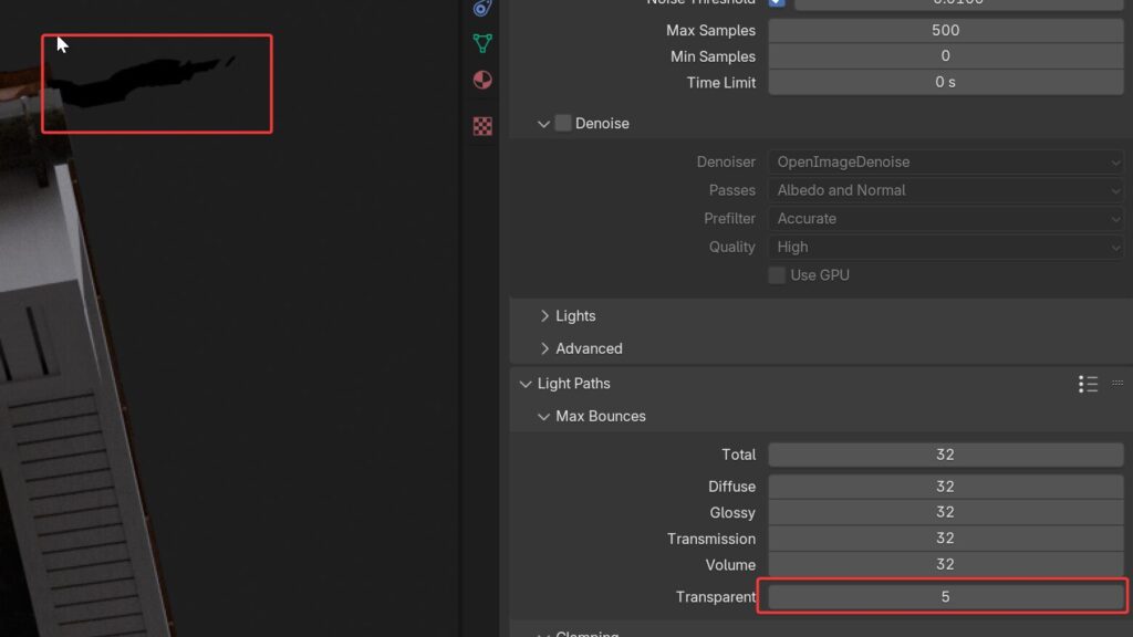
You may also see black edges when looking along the edge of a face. This happens because the alpha map consumes transparent light bounces. Raise the render's transparent bounces to 20 or higher and the black will start to disappear.
Creating your own tiles and ridges
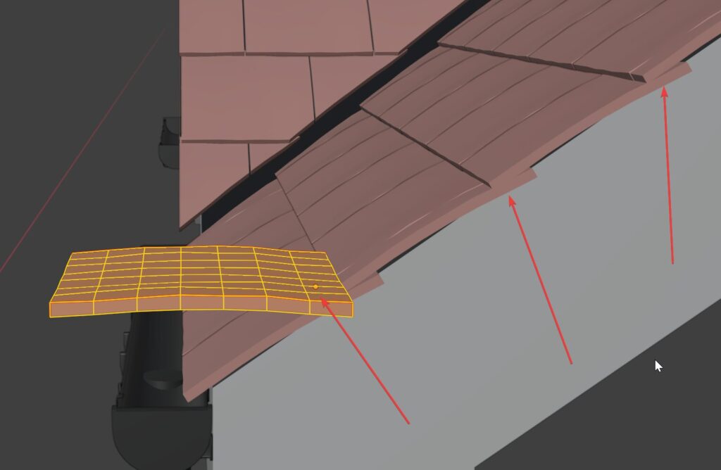
When making tiles, the origin point matters: it determines where the tiles start. Tiles generally overlap slightly along the Y axis up the roof, so set the origin point slightly inside the tile.
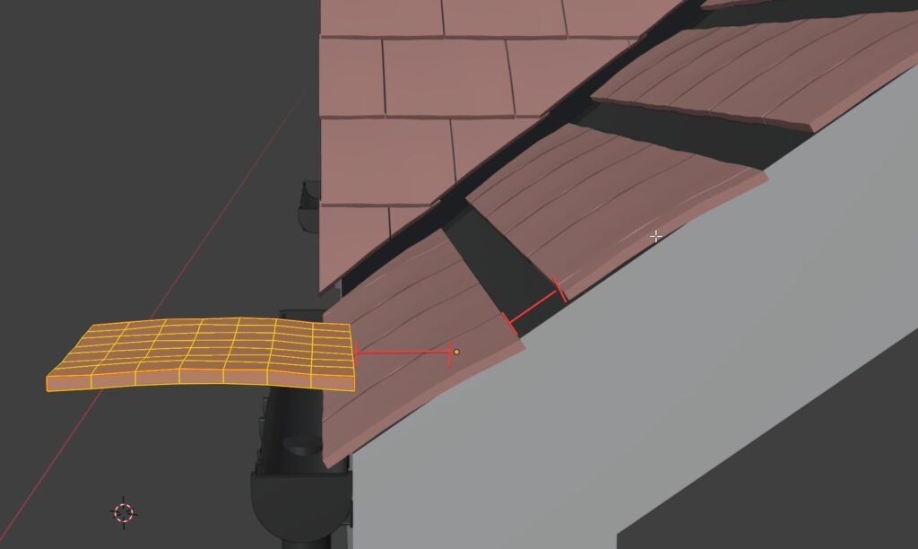
If you set the origin point outside the object, you get a gap.
You can rotate the tile in Edit Mode to rotate all generated tiles.
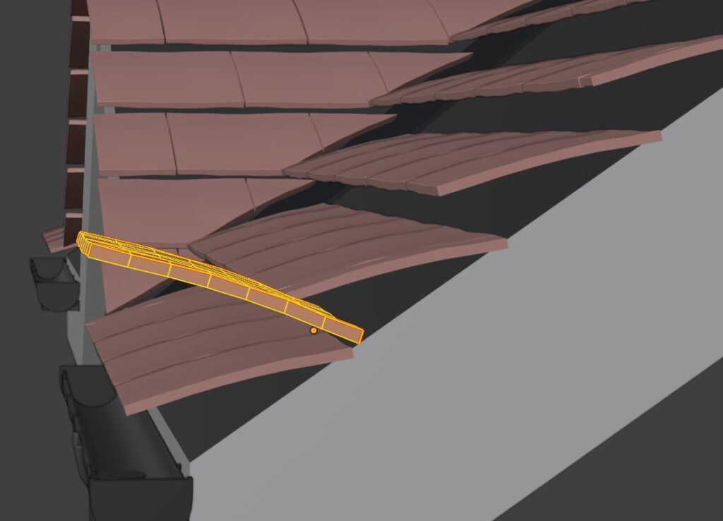
To scale a tile: snap the 3D cursor to the tile's origin point, enter Edit Mode, set the pivot point to the 3D cursor, and scale. All tiles keep their current overlap but get smaller or bigger.
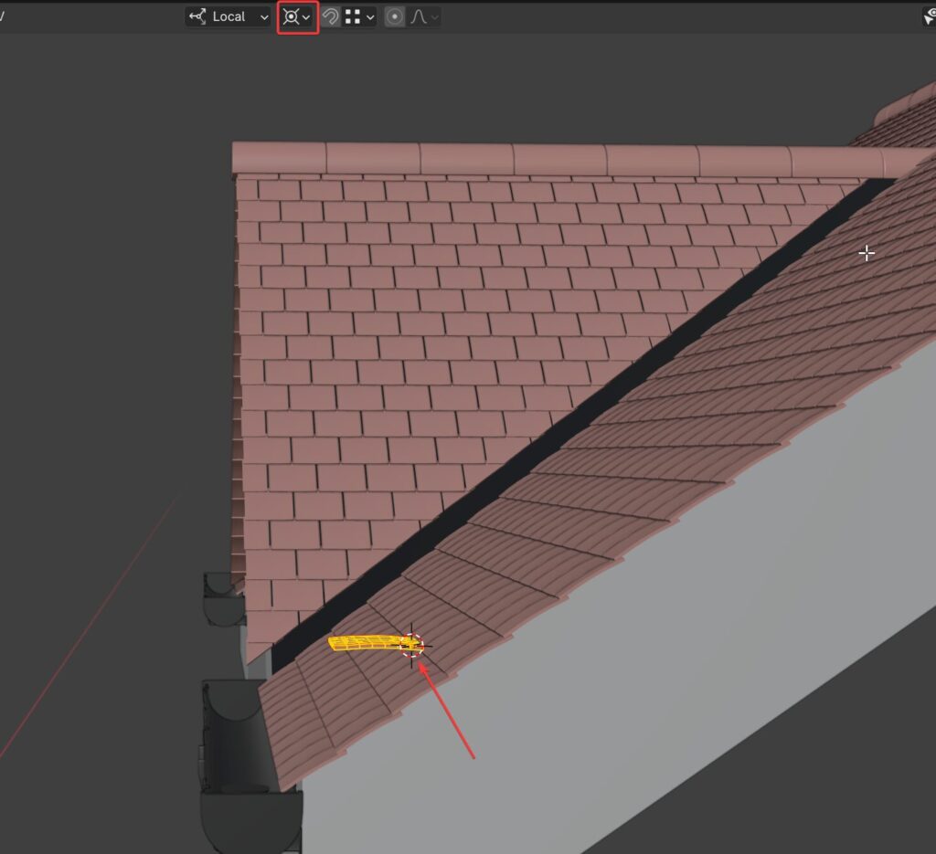
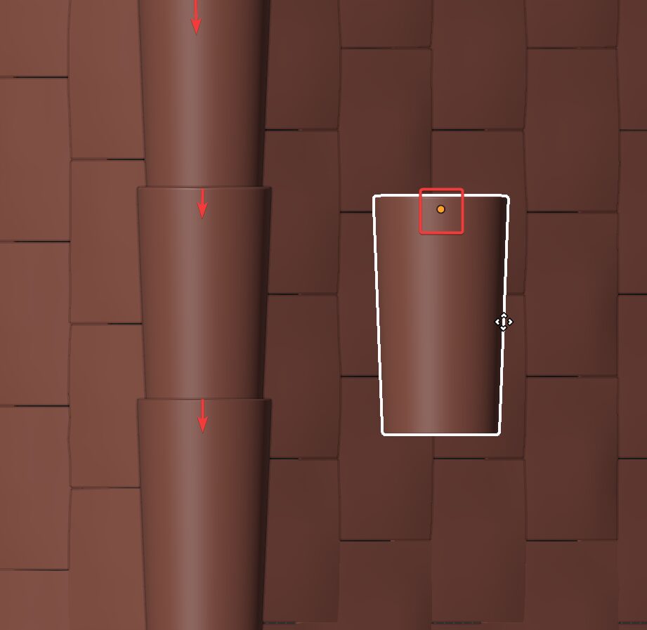
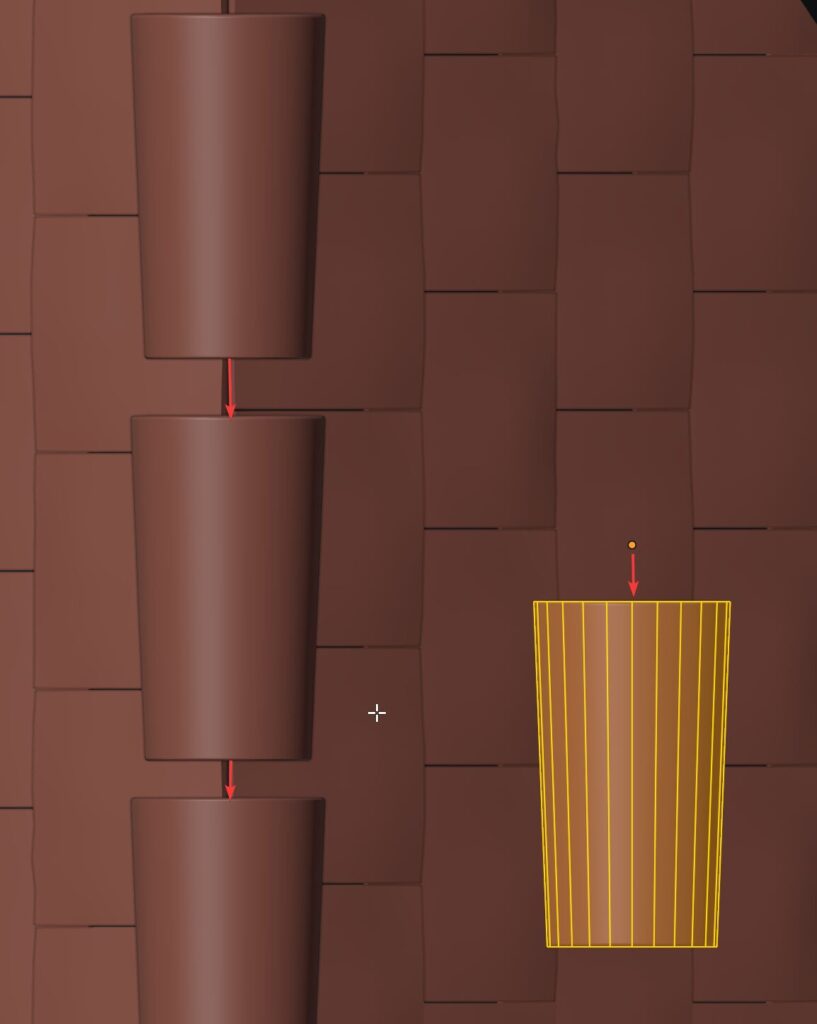
Ridges work the same way: the origin point is what matters. Some ridges need an overlap and some do not. For overlapping ridges, set the origin slightly inside the ridge object; for non-overlapping ones, set it slightly outside.
As with tiles, if you scale the ridge and keep the origin in place, it gets smaller. Watch the origin position to make sure it still looks correct.
Randomization
Enable this parameter to set minimum and maximum values for randomising the tiles.
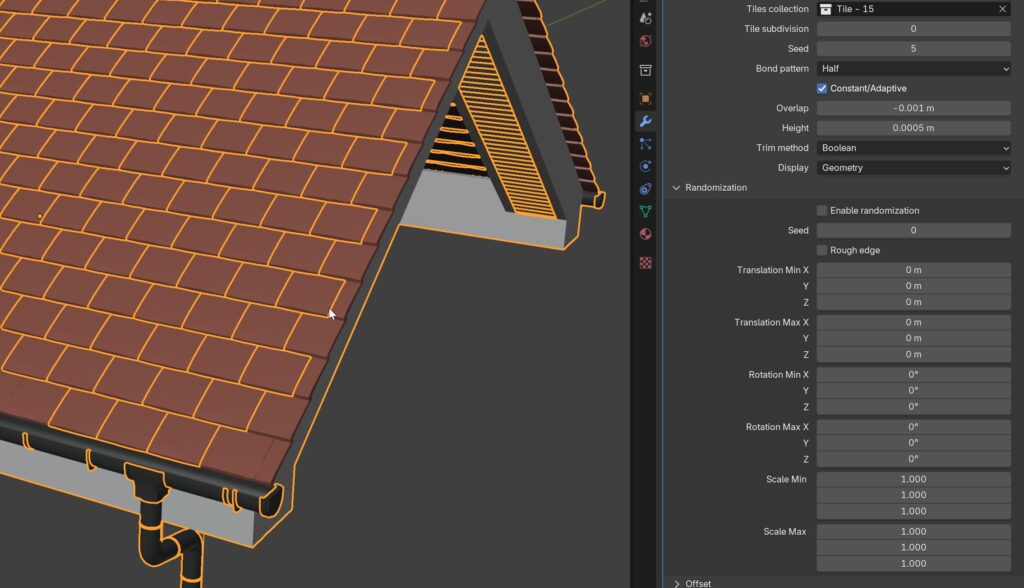
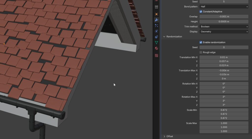
If you want the tiles to look rougher where they are cut, enable Rough Edge. This may look wrong if the randomisation is too strong, as in this example, so use randomisation sparingly.
Offset
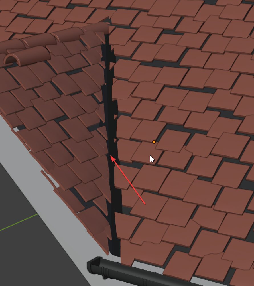
- Edge Offset: offset evenly along all edges.
- Offset Bottom: offset along the bottom edge.
- Offset Side: offset along the sides.
- Remove: an attribute. In Edit Mode, select an edge and use the remove_offset attribute to remove the offset for that specific edge.
Ridge & Hip
Ridges are horizontal, hips are angled.
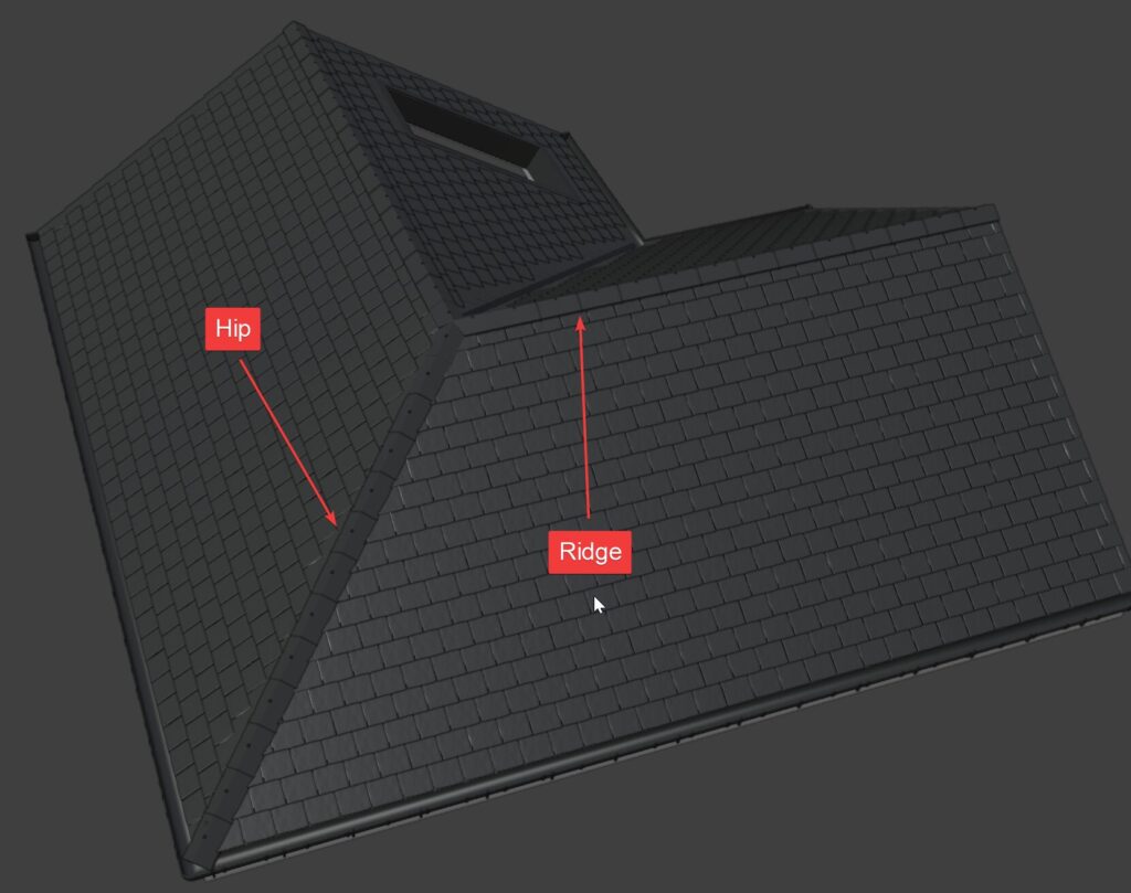
- Ridge Collection: a collection of ridge objects; the system randomises between them.
- Ridge Cap Object: an object placed at the ends of ridges, for closing off the end or adding a decorative piece.
- Ridge Height: offset the ridge from the roof.
- Ridge Overhang: move the ridge out over the edge of the roof.
- Hip Collection: a collection of hip objects; the system randomises between them.
- Hip Cap Object: an object placed at the ends of hips.
- Hip Height: offset the hip from the roof.
- Hip Overhang: move the hip out over the edge of the roof.
- Seed: change the randomisation of collection objects.
- Reverse: some ridges or hips are not symmetrical and the system may face them the wrong way. This attribute fixes that.
- Remove: an attribute to remove hips or ridges you do not want where they were automatically placed.
Fascia & Soffit
These are the parts that protect the roof from below.
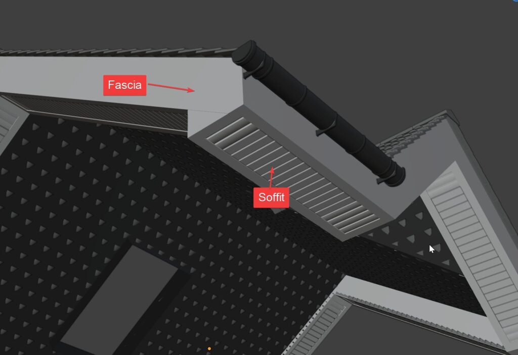
- Show: show or hide these parts.
- Depth: the thickness of the board.
- Remove: an attribute to remove these parts on chosen edges.
- Fascia Material: a specific material for the fascia.
- Soffit Width: the depth of the soffit.
- Soffit Depth: how far up into the object the soffit goes.
- Soffit Additional Height: increase the height of the soffit cover on the inside if you see a gap there.
- Soffit Material: a specific material for the soffit.
- Soffit Geometry: a specific object to use as the planks or underside, useful for grills or planks.
- Soffit Geometry Width: the width of the selected soffit geometry.
- Soffit Geometry Depth: the depth of the selected soffit geometry.
- Soffit Geometry Offset: offset the soffit geometry, for example when planks are cut off at one edge and you want a whole plank there.
Valley
The valley drains rain at the internal edges where tile faces meet.
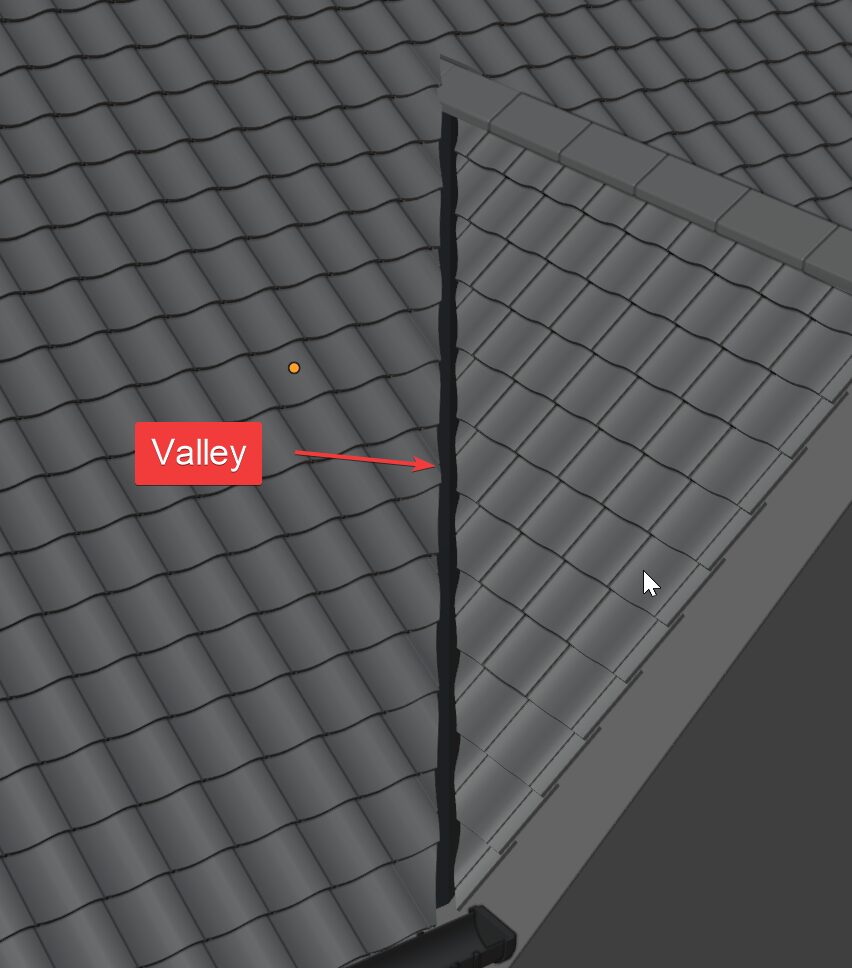
- Show: show or hide the valley.
- Width: the width of all valleys.
- Overlap: how far the valley extends under the tiles. Useful if you can see gaps between valley and tiles.
- Add: an attribute to add a valley to a specific edge that is not detected automatically.
- Remove: remove an automatically added valley you do not want.
- Material: a specific material for the valley.
- Bevel Weight: increase or decrease the bevel strength of the valley.
Flashing
Flashing goes around the edges of window holes in the roof.
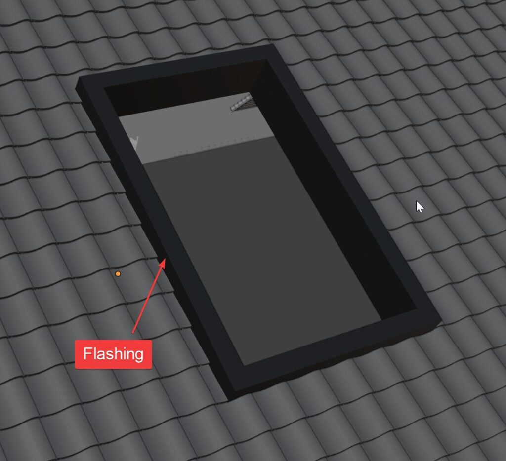
- Show: show or hide the flashing.
- Width: adjust the width.
- Depth: adjust the depth.
- Depth Thickness: offset the lower outside edge to create a lip shape.
- Thickness: the thickness of that lip.
- Shrink: if tiles clip through on the inside edge, shrink the overall shape so they no longer intersect.
- Add: the attribute to apply on edges where you want flashing. If you skip this on window holes, the system will likely try to add fascia and soffit there and it will look broken.
- Material: a specific material for the flashing.
- Bevel Weight: how strong the bevel is.
Gutters
Gutters only appear on edges carrying the add_gutters attribute.
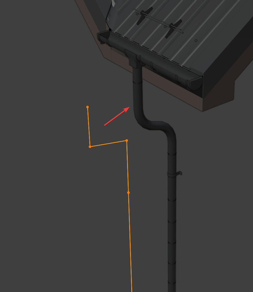
Vertical parts always snap to the closest roof edge. To make a vertical downpipe, all you need is a standalone vertical edge with no connected faces. In the image below, the edge is not connected to the roof at all, yet it snaps correctly to the right spot. You can add as many vertical parts as you need.
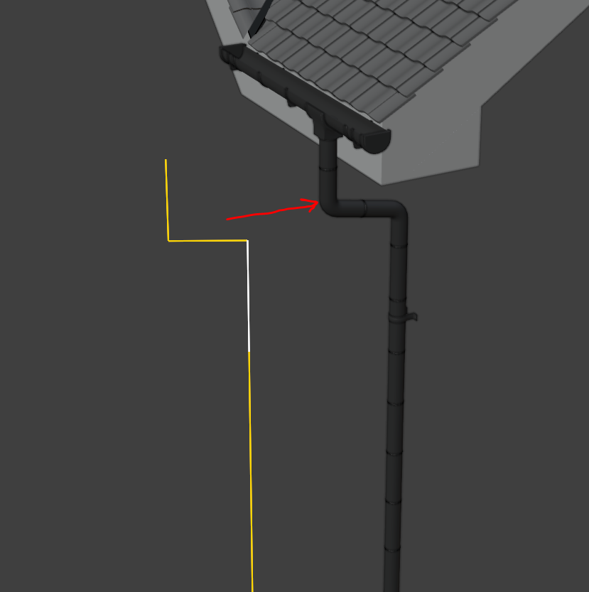
- Show: show or hide the gutter system.
- Add: attribute defining which edges get gutters.
- Horizontal Height: move the horizontal gutter up or down.
- Horizontal Offset: push the horizontal gutter in or out from the roof edge.
- Horizontal Overhang: extend the horizontal gutter outwards.
- Horizontal Profile Curve: the shape used for the horizontal gutter.
- Horizontal Fillet Radius: round the edge of the horizontal gutter.
- Horizontal Fillet Resolution: how smooth the rounding is.
- Horizontal End Points: object used at the end of each horizontal gutter.
- Horizontal Connectors: object used to connect two horizontal sections.
- Horizontal Connectors Distance: spacing between connectors.
- Horizontal Supports: object used as the horizontal gutter support.
- Horizontal Supports Distance: distance between supports.
- Horizontal Supports Offset: move supports in or out.
- Horizontal Surface: the object used to determine the rotation of horizontal gutter supports.
- Vertical Profile Curve: the shape used for the vertical downpipe.
- Vertical Fillet Radius: round the corners of the vertical pipe.
- Vertical Fillet Resolution: how smooth the vertical rounding is.
- Vertical Start Points: object placed at the start of the downpipe.
- Vertical End Points: object placed at the bottom of the downpipe.
- Vertical Connectors: object used between vertical pipe sections.
- Vertical Connectors Distance: spacing between vertical connectors.
- Vertical Supports: object used to support the vertical pipe. Connectors are added automatically, but vertical supports only appear on vertices assigned to a vertex group called Supports.
- Vertical Surface: the object used to determine where vertical pipes go.
- Material: one material for the entire gutter system.
Snow Guard
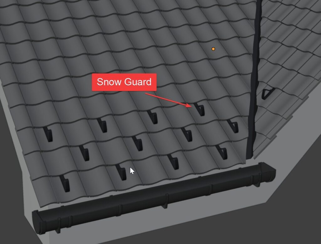
- Show: show or hide the snow guard system.
- Snow Guard Collection: the collection of snow guard objects to use.
- Clip Variation: cycle through the snow guard options within the collection.
- Rows Count: number of snow guard rows.
- Rows Between: space between each row.
- Columns Between: space between each column.
- Offset Row: move rows up or down.
- Offset Column: move columns left or right.
- Flip: flip the start position of the snow guards along the roof face's X axis.
- Horizontal Offset: shift snow guards left or right.
- Vertical Offset: shift snow guards up or down.
- Height: raise or lower the snow guards from the roof surface.
- Rotation: rotate the snow guards.
- Delete Near Edge: remove snow guards close to the roof edge.
- Rails Curve Object: the curve used for snow guard rails. There is one inside the Snow Guard collection, but any profile works.
- Rails Material: material used for the rails.
- Grid Part Object: object used for the grid between the snow guard clips.
- Extend: extend the grid part outwards.
Culling
Camera culling hides tiles that are not visible to the camera. This is great for viewport performance when there are thousands of tiles.
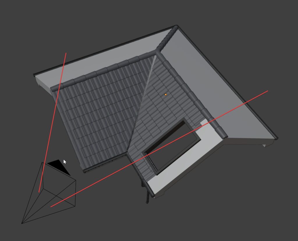
- Enable Camera Culling: hide objects outside the camera view.
- Expand Camera View: add a margin around the camera view to avoid cutting too early.
- Enable Self Culling: hide parts of the object that face away from the camera or sides the camera cannot see.
- Field of View: the camera's field of view.
- Resolution X / Y: the render resolution.
- Aspect X / Y: the pixel aspect ratio.
- Shift X / Y: move the camera view.
- Clip Start / End: the distances where rendering starts and stops.
Texture
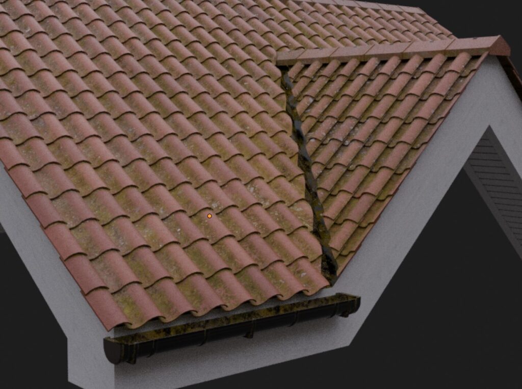
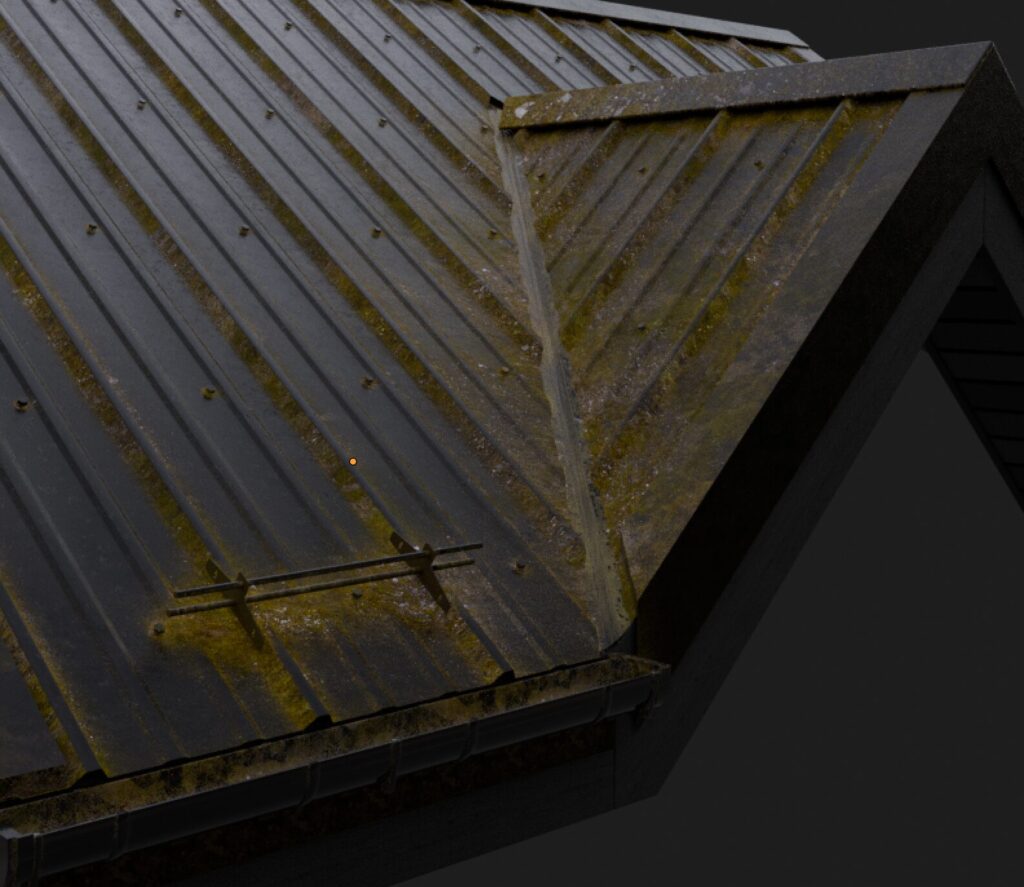
The texture option adds moss to the roof. The moss placement combines several inputs, such as height away from the surface, ambient occlusion, and distance from the edges, which together create a realistic pattern for how moss actually grows on a roof.
There are two controls: Show to display it, and Moss Height, which sets how far from the roof's normal direction the moss appears. It starts close to the roof and gradually moves further away.
Helper
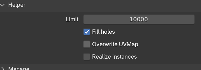
- Limit: limit the total number of tiles being displayed.
- Fill Holes: try to fill any holes left by the boolean trim method.
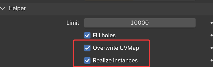
- Overwrite UVMap: works with Realise Instances enabled. Temporarily overwrites the tiles' UV map with the emitter's UV map, useful for texture painting.
- Realise Instances: needed for texture painting or to apply the geometry nodes modifier.
Panel Roof Generator
Initial settings
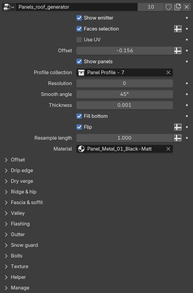
- Show Emitter: hide or show the original base geometry used for the roof system.
- Face Selection: click the Input Attribute Toggle, use the selected_faces attribute, go into Edit Mode, select the faces you want, then assign them in Object Data Properties. Only assigned faces get panels.
- Use UV: use the UV map to control panel locations and orientations. Make sure the roof base mesh is unwrapped and your UV islands sit at 90-degree increments.
- Offset: offset the panels along the X axis. Panels are not duplicated along Y, so there is no Y offset here.
- Show Panels: show or hide the metal panels.
- Profile Collection: a collection containing the profiles for the metal panels, much like the roof tiles, except these must be curve objects. If you have multiple curve profiles they must all be the same length.
- Resolution: add resolution to the input curve profile.
- Smooth Angle: control when the surface shades smooth or flat.
- Thickness: how thick the metal panels are.
- Fill Bottom: fill in the bottom edge when using thickness.
- Flip: run the profiles in the other direction along the X axis.
- Resample Length: can help with the shading of the panels. It may also help the boolean, because it adds geometry to the panel.
- Material: your own material for the metal panels.
Offset
- Edge Offset: offset evenly along all edges.
- Offset Bottom: offset along the bottom edge.
- Offset Side: offset along the sides.
- Remove: an attribute. In Edit Mode, select an edge and use the remove_offset attribute to remove the offset for that edge.
Drip Edge
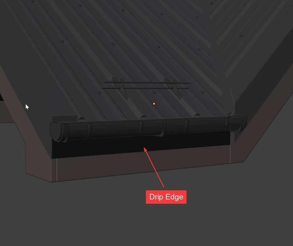
- Show: show or hide the drip edge.
- Width: the width of the drip edge.
- Height: the height of the drip edge.
- Remove: toggle to remove the drip edge.
- Material: the material for the drip edge.
- Bevel Weight: how strong the bevel is.
Dry Verge
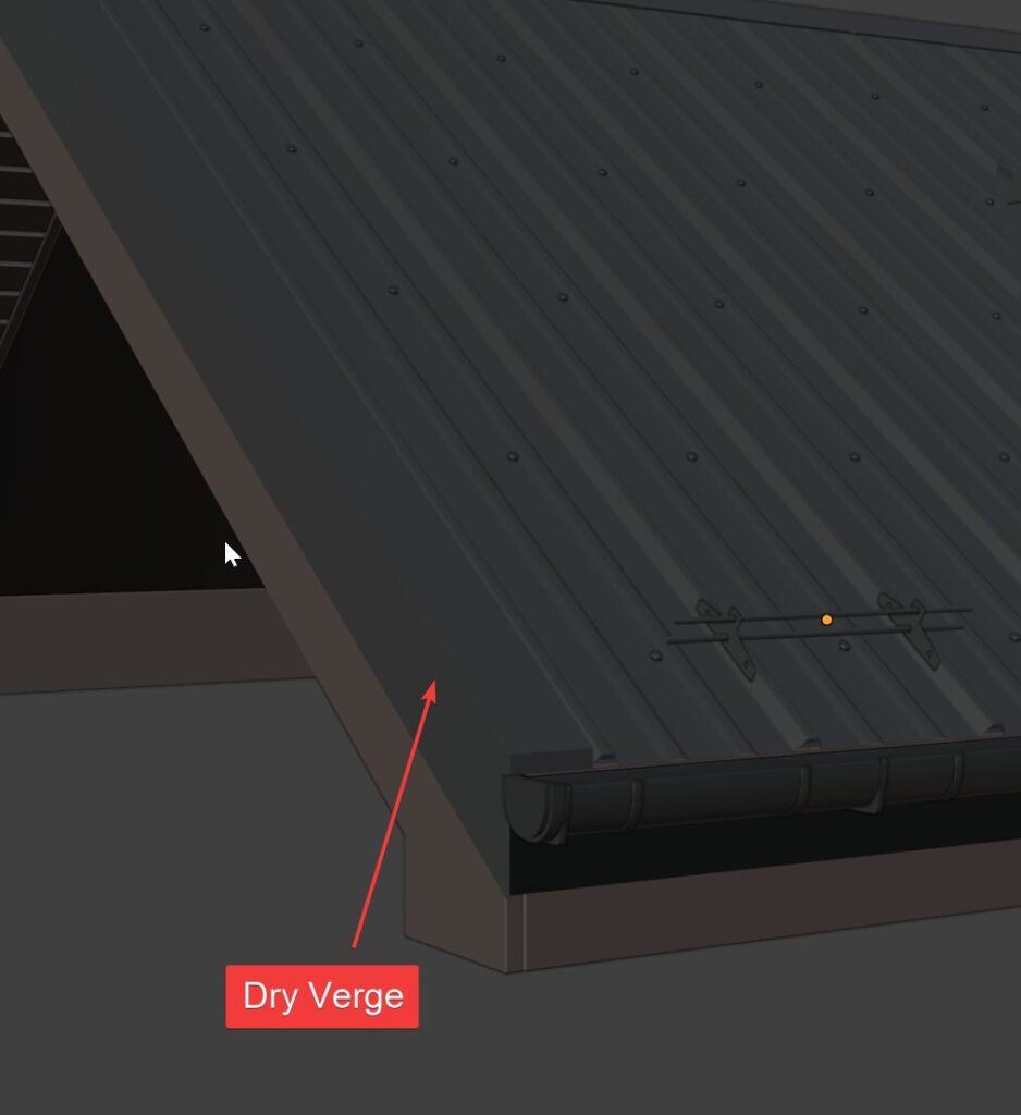
- Show: show or hide the dry verge.
- Width: the width of the dry verge.
- Height: the height of the dry verge.
- Thickness: the thickness of the dry verge.
- Edge Offset: move the dry verge away from the edge.
- Add Cap: add an end cap to the dry verge.
- Close Gap: extend the dry verge to meet the panels.
- Fill Bottom: fill the underside of the dry verge.
- Remove: toggle to remove the dry verge.
- Material: the material for the dry verge.
- Bevel Weight: how strong the bevel is.
Ridge & Hip
Ridges are horizontal, hips are angled. The picture below shows two ridges.
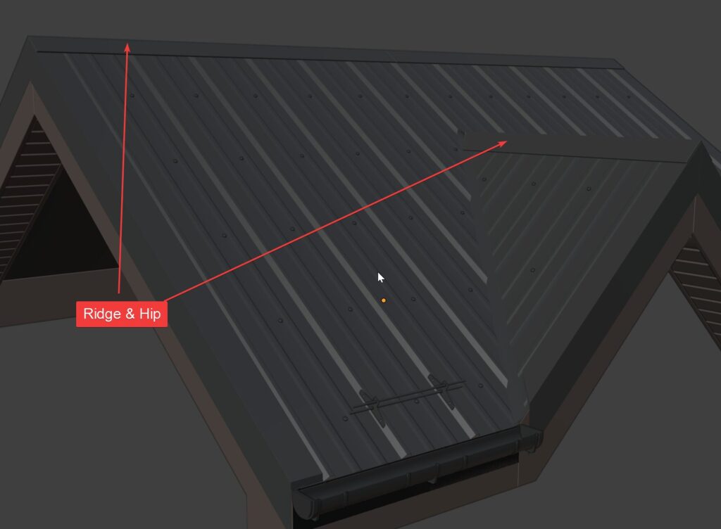
- Show: show or hide the ridge and hip pieces.
- Width: the width of the ridge or hip.
- Thickness: the thickness of the ridge or hip.
- Ridge Overhang: extend the ridge section outward.
- Hip Overhang: extend the hip section outward.
- Close Gap: try to fill small gaps between sections.
- Fill Bottom: fill the underside of the ridge or hip.
- Remove: attribute to remove specific ridge parts.
- Material: the material for the ridge and hip.
- Bevel Weight: the bevel strength.
Fascia & Soffit
These are the parts that protect the roof from below. The parameters are identical to the tile system's Fascia & Soffit section above.
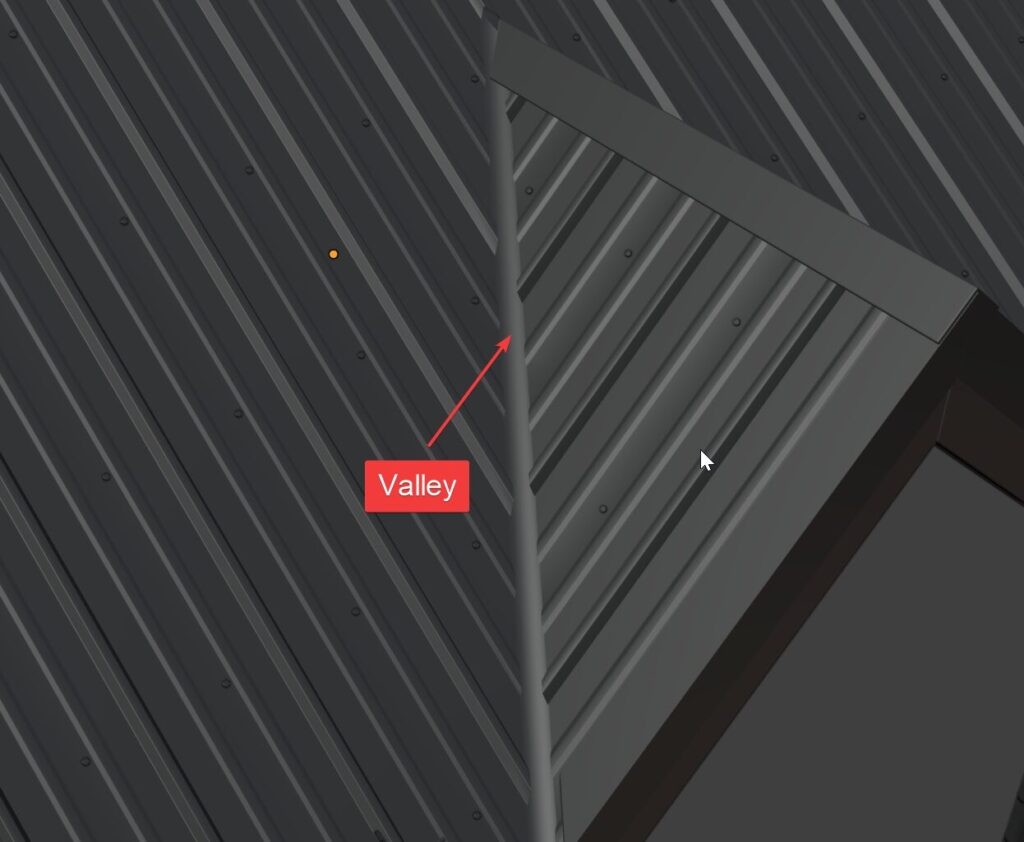
Valley
The valley drains rain where panel faces meet. The parameters match the tile system's valley: Show, Width, Overlap (how far the valley extends under the panels, useful if you see gaps), Add and Remove attributes, Material, and Bevel Weight.
Flashing
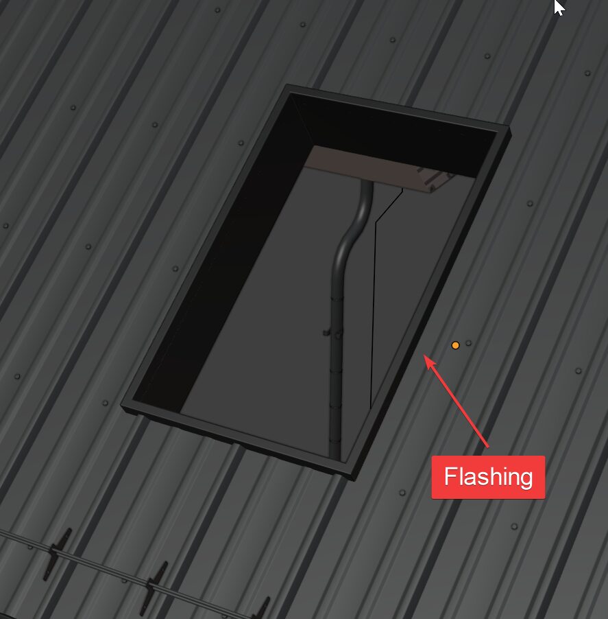
Flashing goes around the edges of window holes, exactly as in the tile system: Show, Width, Depth, Depth Thickness and Thickness for the lip shape, Shrink to stop panels clipping, the Add attribute for the edges that need flashing, Material, and Bevel Weight. If you skip the Add attribute on window holes, the system will try to add fascia and soffit there and it will look broken.
Gutters
Identical to the tile system's gutters: they only appear on edges carrying add_gutters, and standalone vertical edges become downpipes that snap to the closest roof edge.
The parameter list matches the tile system: horizontal height/offset/overhang, profile curves, fillet radius and resolution, end points, connectors and their spacing, supports and their spacing, the Supports vertex group for vertical supports, surfaces for rotation, and one material for the whole gutter system.
Snow Guard
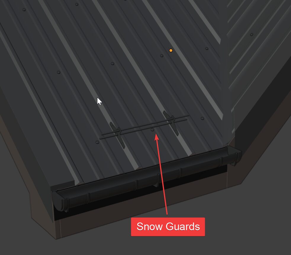
The parameters are identical to the tile system's snow guard section: collection, clip variation, row and column counts and spacing, offsets, flip, height, rotation, delete near edge, rails curve and material, grid part object, and extend.
Bolts
Working much like snow guards, the grid method procedurally adds bolts over the surface in a realistic pattern.
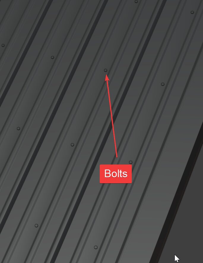
- Show: show or hide the bolts.
- Bolts Collection: the collection of bolt objects to use.
- Variation: use different bolt variations from the collection.
- Rows Count: number of bolt rows.
- Distance Between Rows: spacing between each row.
- Rows Between: number of empty rows between bolt rows.
- Columns Between: number of empty columns between bolt columns.
- Offset Column: shift columns horizontally.
- Flip: flip the bolt layout direction.
- Horizontal Offset: move bolts left or right.
- Vertical Offset: move bolts up or down.
- Height: raise the bolts off the surface.
- Rotation: rotate each bolt.
- Delete Near Edge: remove bolts placed near the mesh edge.
Texture
The same moss system as the tile roof: Show to display it, and Moss Height (0 to 1) to control how far from the roof's normal direction the moss appears.
Helper
- Overwrite UVMap: works with Realise Instances enabled. Temporarily overwrites the panels' UV map with the emitter's UV map, useful for texture painting.
- Realise Instances: needed for texture painting or to apply the geometry nodes modifier.
Texture painting
Texture painting lets you paint directly on the tiles or panels. Each tile has its own UV map while the main roof surface has its own, so to paint across the surface you paint onto the surface of the object and then feed that painted mask into the tiles' material.
- Enable Overwrite UVMap and Realise Instances, and make sure your main roof object is unwrapped with no overlapping UV islands.
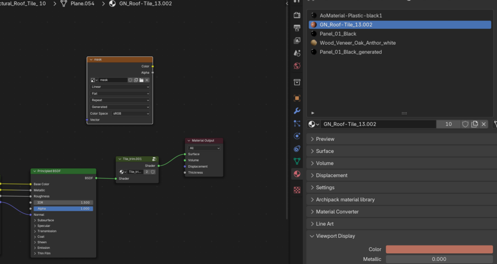
- In the tile material, create a new image called mask (or anything unique).
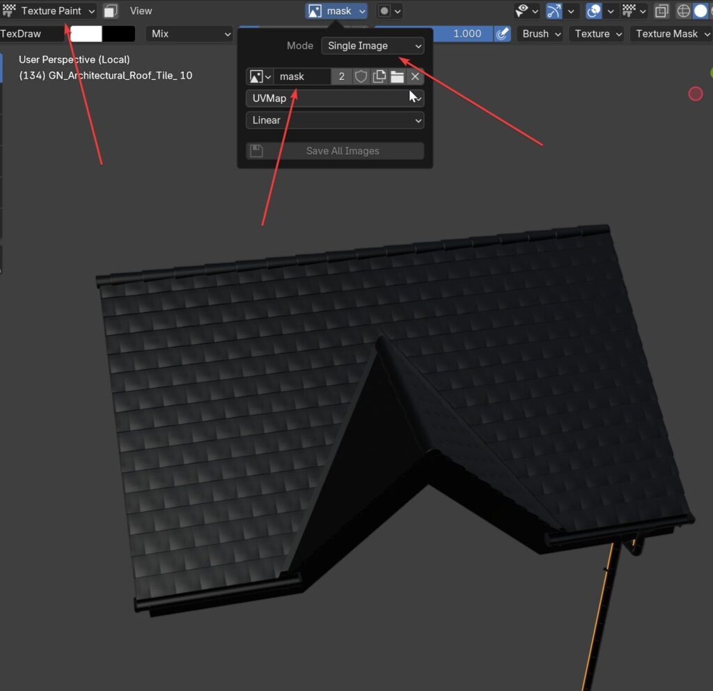
- Go to Texture Paint mode, set the painting mode to Single Image, and pick your new mask image.
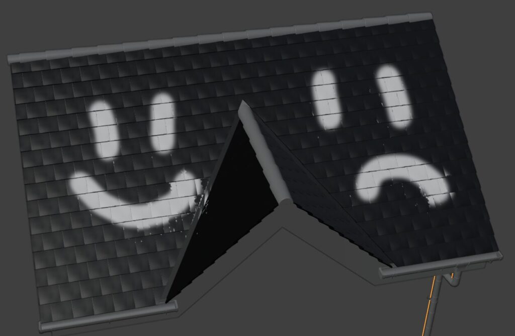
- Paint onto the roof. Simple strokes work, or use special brushes to paint any effect directly onto the roof.
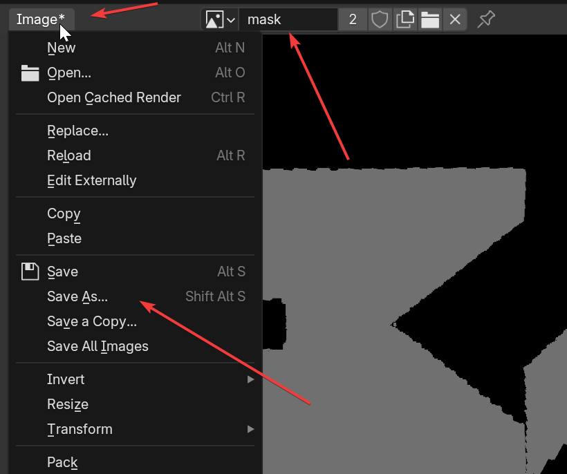
- In the UV/Image editor, find the mask, click Image, then Save As so you do not lose the painted mask.
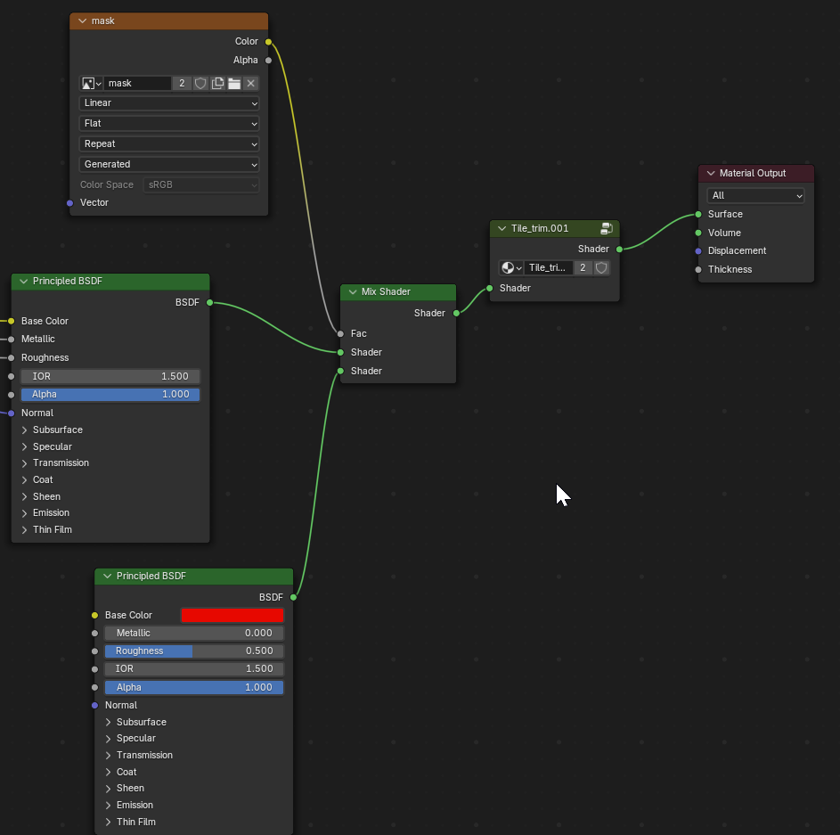
- In the material editor, add a Mix Shader and a second material (anything you like). Plug the mask into the Mix Shader factor.
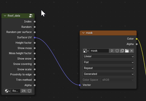
- Add the Roof_data node group and plug its Surface UV output into the mask's Vector input.
- Disable Overwrite UVMap and Realise Instances.
- Render and see the painted result.